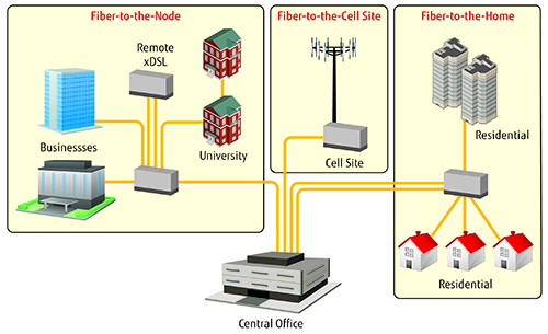
Fiber networks are the foundation on which telecom networks are built. In the early planning stages of network transformation or expansion, it is imperative that operators perform a complete and thorough assessment of the underlying fiber infrastructure to determine its performance capabilities as well as its limits. Industry experts predict as many as one-third of the fiber networks will require modifications to the existing systems.
Front-end fiber analysis ensures key metrics are met and the fiber is at optimum performance levels to handle the greater bandwidth required to transport data-intensive applications over longer distances. This will save the service provider time and money and prevent delays in the final test and turn-up phase of the expansion or upgrade project.


Potential Problems & Testing Options
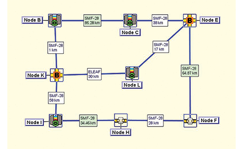
Fiber networks are comprised of multiple types, ages and quality of fiber all of which significantly impact the fiber infrastructure and transmission capabilities. Additionally, the fiber may come from several different fiber providers. The net result is there are several potential problem areas with fiber transmission including:
- Aging fiber optics – Some fiber optic networks have been in operation for 25+ years. These legacy fiber systems weren’t designed to handle the sheer volume of data that is being transmitted on next generation networks.
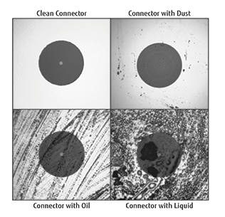
- Dirty and damaged connectors – Dirty end faces are one of the most common problems that occur at the connectors. Environmental conditions such as oil, dirt, dust or static-charged particles can cause contamination.
- Splice loss – Fibers are generally spliced using fusion splicing. Variations in both fiber types (manufacturers) and the types of splices that are being used (fusion or mechanical) can all result in loss.
- Bending – Excessive bending of fiber-optic cables may deform or damage the fiber. The light loss increases as the bend becomes more acute. Industry standards define acceptable bending radii.
Fiber characterization testing evaluates the fiber infrastructure to make sure all the fiber, connectors, splices, laser sources, detectors and receivers are working at their optimum performance levels. It consists of a series of industry-standard tests to measure optical transmission attributes and provides the operator with a true picture of how the fiber network will handle the current modernization as well as future expansions. For network expansions that require new dark fiber, it is very important to evaluate how the existing fiber network interacts with the newly added fiber to make sure the fiber meets or exceeds the service provider’s expectations as well as industry standards such as TIA/ANSI and Telcordia.
There are five basic fiber characterization tests:
- Bidirectional Optical Time-Domain Reflectometer (OTDR) – sends a light pulse down the fiber and measures the strength of the return signal as well as the time it took. This test shows the overall health of the fiber strand including connectors, splices and fiber loss. Cleaning, re-terminating or re-splicing can generally correct problems.
- Optical Insertion Loss (OIL) – measures optical power loss that occurs when two cables are connected or spliced together. The insertion loss, is the amount of light lost. In longer distances, the light loss can cause the signal strength to weaken.
- Optical Return Loss (ORL) – sends a light pulse down the fiber and measures the amount of light that returns. Some light is lost at all connectors and splices. Dirty or poorly mated connectors cause scattering or reflections and result in weak light returns.
- Chromatic Dispersion (CD) – measures the amount of dispersion on the fiber. In single-mode fiber, the light from different wavelengths travels down the fiber at slightly different speeds causing the light pulse to spread. Additionally, when light pulses are launched close together and spread too much, information is lost. Chromatic dispersion can be compensated for with the use of dispersion-shifted fiber (DSF) or dispersion compensation modules (DCM’s.)
- Polarization Mode Dispersion (PMD) – occurs in single-mode fiber and is caused by imperfections that are inherent in the fiber producing polarization-dependent delays of the light pulses. The end result is the light travels at different speeds and causes random spreading of optical pulses.
Once the fiber characterization is complete, the service provider will receive a detailed analysis of the condition of the fiber plant including: location of splice points and pass-troughs as well as assignments of panels, racks and ports. They will also know if there is any old fiber that will not be able to support higher data rates now or for future upgrades. More importantly, by doing the fiber characterization prior to transforming or expanding their telecom network, service providers can eliminate potential risks with the fiber infrastructure that can result in substantial delays during the final test and turn-up phases.