In the previous series of tutorials, Fujitsu’s Francois Moore explained the key functionality and benefits that underpin next-generation CDC-G ROADM: Colorless, Directionless, Contentionless, and Gridless.
Even as networks struggle to adapt to changing customer patterns and surging demands for bandwidth, telecommunication providers must continue to provide reliable, cost-efficient services. This means delivering more dynamic capacity and reach at the lowest cost per bit. In today’s high-speed optical networks, two key variables affecting capacity and cost are baud rate and modulation density; both can be managed and optimized.
Transmitting Data—Like Delivering Parcels
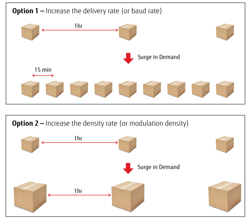
The difference between baud rate and modulation density can be compared to a typical package delivery service. On a normal day, the service delivers 24 identical boxes to the same place, one an hour. Suddenly, demand quadruples; and the service must deliver 96 boxes in the next 24 hours.
One way to meet the increased demand is simply to deliver each box faster, instead of delivering one per hour they could deliver one every 15 minutes. In other words, by increasing the delivery rate, the service could meet demand. But what if they don’t have enough trucks or drivers to make 96 deliveries in one day?
Another option is to deliver one large container with four smaller boxes inside, once every hour. Using this method, the service meets demand by increasing the density rate for each delivery in a 24-hour period.
A third option is to increase the delivery rate and the delivery density, sending multi-box containers at regular intervals. Using either or both approaches, the package delivery service can meet customer demand by choosing the method that best fit their available resources and customer needs.
Send the same shipment faster or make shipments bigger. Sending bits over an optical fiber isn’t that different. Think of the baud rate as the frequency of deliveries, and the modulation density is how many packages can be delivered in a shipment. Let’s taker a closer look at both.
Increasing Bit Rate with Denser Modulation Schemes
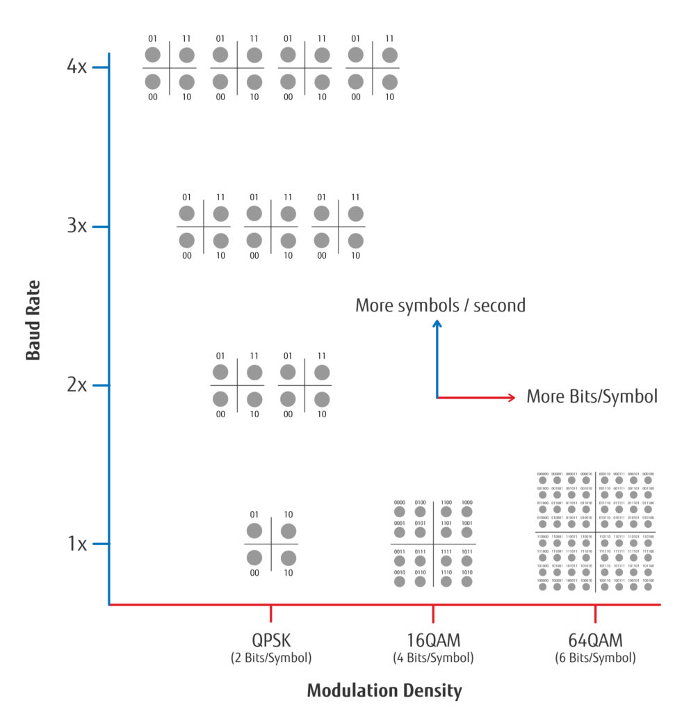
In Figure 2, the first modulation technique is the quadrature phase shift-keying (QPSK,) indicated by the four circles. Every time a QPSK symbol is sent, information for two bits is transmitted. As you move to the right on the horizontal axis the modulation schemes become denser. Four bits per symbol yields a 16QAM (quadrature amplitude modulation) transmission rate, with 16 different states of polarization. At 16QAM, each pulse transmits four bits of data, which is then decoded when the signal is received. On the far right of the horizontal axis is 64QAM, in which each pulse sends six bits of data per symbol and 64 different positions. Assuming the pulses are sent at a constant rate, as the modulation density increases, so does the bit rate transmission.
If transmitting at 30 symbols per second:
- For QPSK, each symbol contains two bits, or 60 bits per second
- For 16QAM, each symbol contains four bits, or 120 bits per second
- For 64QAM, each symbol contains six bits or 180 bits per second
Increasing Bit Rate with Faster Baud Rates
The second way to increase capacity is to keep modulation fixed and increase the baud rate. In the earlier example, a QPSK symbol transmits two bits. Rather than sending 30 symbols a second, why not send 60 per second, or even 100? By sending the information faster (more frequently) you increase the number of bits transmitted over a defined time frame. Assume we keep the modulation at QPSK (two bits/symbol) and increase the symbol’s speed of transmission, we can achieve the following:
- Sending 30 symbols per second transmits a total of 60 bits per second
- Sending 60 symbols per second transmits a total of 120 bits per second
- Sending 90 symbols per second transmits a total of 180 bits per second
Whether you increase the modulation density and keep the baud rate constant, or vice-versa, the increase in the bit rate is the same. The bottom line? Both approaches yield the same results. But be careful, the two are not totally equal. For one thing, there are tradeoffs to increasing modulation density in terms of distance.
Using Modulation Density and Baud Rate Together
New transponders allow the user to increase both the modulation density as well as the baud rate to generate even larger transmission rates.
For example: You can transmit 60 bits per second using QPSK modulation (two bits per symbol) with a symbol transmission rate of 30 symbols per second. By setting the transponder to use 64QAM modulation (six bits per symbol) and increase the baud rate to 60 symbols per second, the overall transmission rate increases six-fold, to 360 bits per second. The increase from QPSK to 64QAM triples the bits per symbol and the baud rate increase provides the other 2× improvement.
The second way to increase capacity is to keep modulation fixed and increase the baud rate. In the earlier example, a QPSK symbol transmits two bits. Rather than sending 30 symbols a second, why not send 60 per second, or even 100? By sending the information faster (more frequently) you increase the number of bits transmitted over a defined time frame. Assume we keep the modulation at QPSK (two bits/symbol) and increase the symbol’s speed of transmission, we can achieve the following:
- Sending 30 symbols per second transmits a total of 60 bits per second
- Sending 60 symbols per second transmits a total of 120 bits per second
- Sending 90 symbols per second transmits a total of 180 bits per second
Whether you increase the modulation density and keep the baud rate constant, or vice-versa, the increase in the bit rate is the same. The bottom line? Both approaches yield the same results. But be careful, the two are not totally equal. For one thing, there are tradeoffs to increasing modulation density in terms of distance.
Going the Distance versus Carrying a Wide Load
Note that in Figure 2, the circles at 64QAM (representing data bits) are closer to each other than the circles at QPSK on the far left. This means they have less noise tolerance. As you increase the modulation density, the transmission becomes more sensitive to noise. When received, the signal will be mapped near the circle’s center but not directly on it. If the constellation mappings are especially dense, the receiver may even make a mistake decoding the signal. When opting to use a denser modulation, be aware that the distance a signal can be transmitted is reduced.
Baud rate has its advantages and tradeoffs, as well. As the baud rate increases, the bandwidth can double without sacrificing distance; but the spectral width of the wavelength will be wider. For example, a 100Gb/s wavelength using a QPSK transmission signal fits inside a 50GHz channel. But if the baud rate is doubled, the resulting 200Gb/s wavelength cannot be transmitted using the 50GHz channel. The wavelength is wider and requires 75GHz slots.
That is a problem for legacy fixed-grid ROADMs that have 50GHz slots. Each side of the wider wavelength is clipped, degrading the signal. However, this can be overcome using an SDN controller and flexible grid technology. Flexible grid is standard technology on next generation ROADM networks, providing the ability to adjust the width of a wavelength on a per channel basis. When a circuit is provisioned, the width of the channel can be configured as well, allowing users to ensure that the channel width matches the baud rate on the transponders.
Balancing Bandwidth and Budget
Of course, the other variable that always needs to be considered is cost. More specifically, in situations where the distances are the same, which approach will deliver the best balance of bandwidth and cost? Well, that depends on the distance.
For longer distances, say 3000 kilometers, service providers often find that increasing baud rate yields the best results. Transmitting at 1× the baud rate, using DP-QPSK modulation provides 96 100G (per wavelength) channels. 96 × 100 yields a total capacity of 9.6 terabits. Doubling the baud rate, doubles the bit rate of the wavelength to 200G. The wider wavelength reduces the number of channels to 64 for a total capacity of 12.8 terabits (64 × 200). The bottom line result for this scenario? Doubling the baud rate increases capacity 33-percent, from 9.6 to 12.8 terabits, while the number of transponders needed is reduced from 96 to 64.
Alternatively, for shorter distances, increasing the modulation density provides some advantages versus increasing the baud rate. Transmitting over smaller distances creates less noise which allows the carrier to use a denser modulation. As an example, let’s assume that a carrier needs to transmit 2 × 100G circuits over a short distance. The carrier can choose to operate at QPSK with two transponders and two 100G wavelengths. This approach uses 100Ghz of spectrum (two wavelengths at 50Ghz) and requires two transponders. Or, the carrier can operate at 16QAM with a single transponder and a single wavelength for both 100G circuits. This approach uses 50Ghz of spectrum (one wavelength at 50Ghz) and requires only a single transponder.
In general, if the distance is short, it is more cost effective to increase the modulation density and reduce the number of required transponders. As the transmission distance increases, at some point, it becomes more effective to increase the baud rate to reduce the equipment cost.
Your tools are Only as Powerful as Your Knowledge
Like most network design challenges, trying to decide how to use baud rate and modulation density for any given project rarely yields a black and white answer. That’s because these two crucial components of capacity design are simply tools. The key is knowing how, when and where to use them.
Looking ahead, new and emerging transponder technologies will provide operators with an increased number of possible combinations to optimize the transmission capacity within their available spectrum. Different combinations of baud rate and modulation density are now available to help carriers find the optimal mix which minimizes the total cost of equipment required to transport ever larger traffic loads over distances ranging from short single spans to long haul.
To see how capable today’s new generation of transponders are, I encourage you to check out the Fujitsu 1FINITY Transport family of optical transponders. It offers flexible baud rate and modulation density, among other variable performance features. Click here for more information on these T-series products listed in the “In this Section” menu.

